

Credits: This tutorial is inspired from my lab module in my uni.Thanks to my lecturer Dr Ejat for teaching me Raspberry Pi and MQTT .
PART 1- INSTALL MQTT FIRST
0.To understand what is mqtt pls watch
1.First step update and upgrade your pi.


2.Install the broker Mosquito and type y

3.Enable the mosquito broker service to be run in the background.

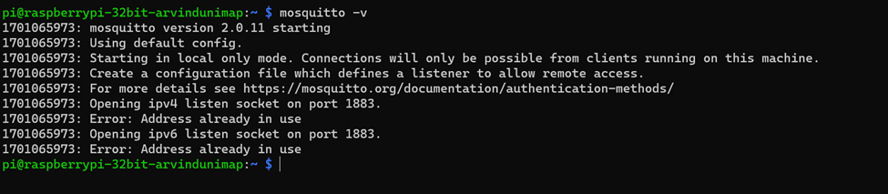
4.Check whether Mosquito is running or not.
5.After that open mosquito configuration file using the command below and press ENTER.

6.At the end of the code add these two lines so to set listening port for the Mosquito broker and allow non-password access.

7.Press CTRL+X to exit .Press Y and Enter so that the changes will be saved.
8.Restart the mosquitto

9.We are done with setting up in pi .Now we have install MQTTX software in laptop to establsih communication betwwen pi and the laptop.
Download link-https://mqttx.app/
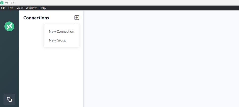
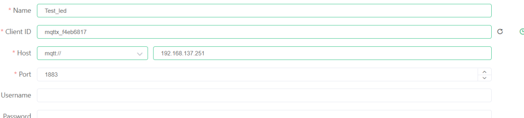
10.Open the software.Click on New connectoon.
11.Enter the details.Name =any name.Ip address=yours.Client id=any.After that click connect.

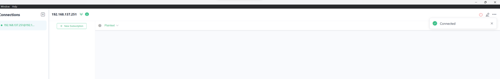
12.You can see the connected symbol
13.Click on +NEW Subcription to publish messages.
14.Name any name ,mine LED.

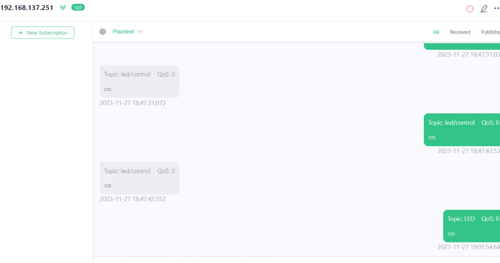
15.Topic name is LED.Message =on.

PART 2 – CONTROLLING LED USING MQTTX AND PAHO MQTT
IN THIS PART, WE ARE NOT GOING TO USE SECONDARY MICROCONTROLLER BUT THE PI ITSELF. IN NEXT TUTORIAL , WE WILL DO THAT.
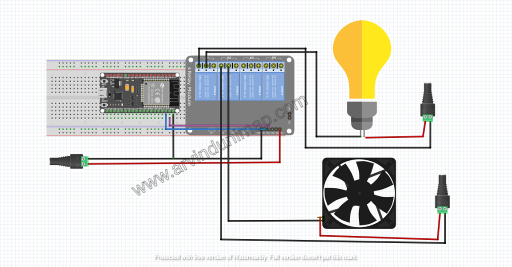
HARDWARE CONFIGURATION
Connect led to GPIO 21 pin 40.Thats all
CODING – replace with your ip address
import RPi.GPIO as GPIO
import paho.mqtt.client as mqtt
import time

GPIO.setwarnings(False)  # Ignore GPIO pin in use warning

# GPIO setup
led_pin = 21  # GPIO pin connected to the LED (change to your pin number)
GPIO.setmode(GPIO.BCM)
GPIO.setup(led_pin, GPIO.OUT)
GPIO.output(led_pin, GPIO.LOW)  # Ensure the LED is initially off

# MQTT settings
broker_address = "192.168.137.251"  # Raspberry Pi IP
client = mqtt.Client("LED")  # Client name

# Callback function to handle MQTT messages
def on_message(client, userdata, message):
    msg = str(message.payload.decode("utf-8"))
    print("Received message: " + msg)
    if msg == "on":
        GPIO.output(led_pin, GPIO.HIGH)  # Turn on LED
    elif msg == "off":
        GPIO.output(led_pin, GPIO.LOW)  # Turn off LED

# Connect to MQTT broker and subscribe to LED topic
client.connect(broker_address)
client.subscribe("LED")
client.on_message = on_message
client.loop_start()

try:
    while True:
        time.sleep(1)
except KeyboardInterrupt:
    GPIO.cleanup()
    client.disconnect()
    client.loop_stop()
OUTPUT
1.USING LAPTOP
MQTTX CONFIGURATION IN LAPTOP


2.USING PHONE
MQTTX CONFIGURATION IN PHONE


IMPORTANTN NOTE :YOU CAN ONLY CONNECT ONE MQTT CLIENT TO ONE BROKER WITH THE CODING ABOVE
TO CONNECT TWO MQTT CLIENT TO ONE MQTT BROKER YOU HAVE TO USE SEPARATE MQTT CLIENT ID.
IN LAPTOP I USED TOPIC LED , MESSAGE =ON
IN PHONE, TOPIC LED2 , MESSAGE =OFF
OUTPUT

THE CODE IS BELOW:
import RPi.GPIO as GPIO
import paho.mqtt.client as mqtt
import time

GPIO.setwarnings(False)  # Ignore GPIO pin in use warning

# GPIO setup
led_pin = 21  # GPIO pin connected to the LED (change to your pin number)
GPIO.setmode(GPIO.BCM)
GPIO.setup(led_pin, GPIO.OUT)
GPIO.output(led_pin, GPIO.LOW)  # Ensure the LED is initially off

# MQTT settings
broker_address = "192.168.137.251"  # Raspberry Pi IP

# First MQTT client (LED)
client1 = mqtt.Client("LED")  # Client name for LED 1

# Second MQTT client (LED2)
client2 = mqtt.Client("LED2")  # Client name for LED 2

# Callback function to handle MQTT messages for LED1
def on_message_led1(client, userdata, message):
    msg = str(message.payload.decode("utf-8"))
    print("Received message (LED1): " + msg)
    if msg == "on":
        GPIO.output(led_pin, GPIO.HIGH)  # Turn on LED
    elif msg == "off":
        GPIO.output(led_pin, GPIO.LOW)  # Turn off LED

# Callback function to handle MQTT messages for LED2
def on_message_led2(client, userdata, message):
    msg = str(message.payload.decode("utf-8"))
    print("Received message (LED2): " + msg)
    # Process messages for LED2 (add your logic here)

# Connect LED1 to MQTT broker and subscribe to LED topic
client1.connect(broker_address)
client1.subscribe("LED")
client1.on_message = on_message_led1
client1.loop_start()

# Connect LED2 to MQTT broker and subscribe to another topic (customize as needed)
client2.connect(broker_address)
client2.subscribe("LED2_TOPIC")  # Subscribe to a different topic for LED2
client2.on_message = on_message_led2
client2.loop_start()

try:
    while True:
        time.sleep(1)
except KeyboardInterrupt:
    GPIO.cleanup()
    client1.disconnect()
    client1.loop_stop()
    client2.disconnect()
    client2.loop_stop()
THANK YOU FOR READING
for any queries contact me at https://wa.link/ctghed


You must be logged in to post a comment.