
LAB 1-HARDWARE AND BASIC PROGRAMMING USING ARDUINO IDE
Hardware required
1.Esp32
2.Ldr
3.Lm35
4.10k resistor
5.Breadboard
6.Led
7.Micro USB Cable
Software required
1.Arduino Ide
Part 1- Installing Arduino IDE and Configuring ESP32 in Arduino Ide
a)Installing Arduino IDE
1.Download and install Arduino IDE from Arduino’s website.
https://www.arduino.cc/en/Main/Software
b)Adding Boards Manager URL
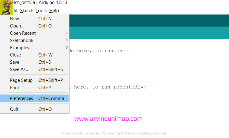
1.Open File>Preferences
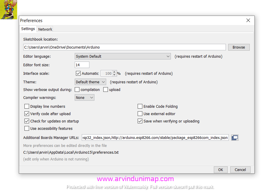
2. Click Additional Boards Manager URL’s icon add the url below.
https://dl.espressif.com/dl/package_esp32_index.json
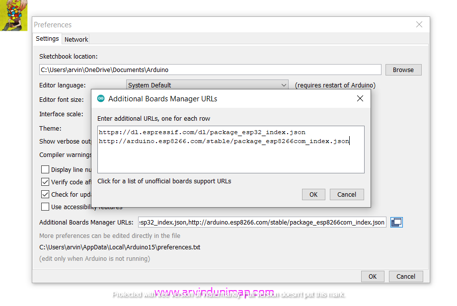
If you have extra urls you can use a comma to add additional urls.
3.Install ESP32 Serial Driver so that ESP32 will be detected through the usb data cable.
https://www.silabs.com/products/development-tools/software/usb-to-uart-bridge-vcp-drivers
c)Installing library for ESP32
1.Open Arduino Ide and click Tools>Board>Boards Manager.
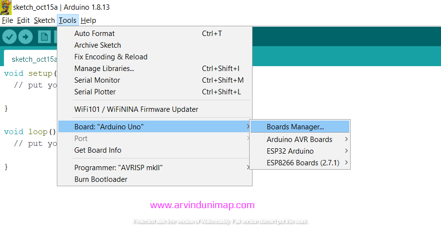
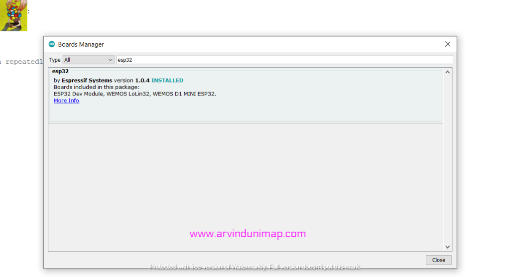
2.Search for ESP32 and click install.It will install the library for ESP32.
*In my case , I have already installed.
Part 2-Blinking Led on Esp 32
1.Connect the wiring as shown in the circuit below.
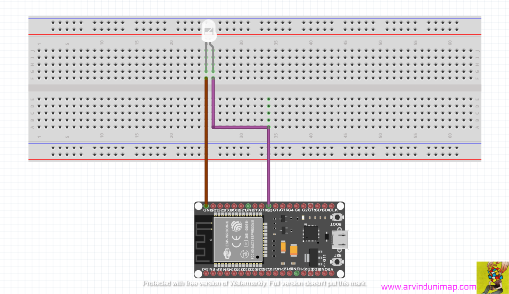
Ground – cathode of the led
GPIO 5 – anode of led
2.Next compile this coding below to blink the led
///www.arvindunimap.com

const int ledPin = 5;
void setup() {
  // setup pin 5 as a digital output pin
  pinMode (ledPin, OUTPUT);
}
void loop() {
  digitalWrite (ledPin, HIGH);	// turn on the LED
  delay(500);	// wait for half a second or 500 milliseconds
  digitalWrite (ledPin, LOW);	// turn off the LED
  delay(500);	// wait for half a second or 500 milliseconds
}
3.This will be the output.
Part 3-Testing the LDR resistor
1.Connect the cicuit a shown below.
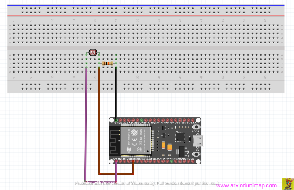
2.Use the coding below.
///www.arvindunimap.com

// the setup routine runs once when you press reset:
void setup() {
  // initialize serial communication at 9600 bits per second:
  Serial.begin(9600);
}

// the loop routine runs over and over again forever:
void loop() {
  // read the input on analog pin 34:
  int sensorValue = analogRead(34);
  // print out the value you read:
  Serial.println(sensorValue);
  delay(1);        // delay in between reads for stability
}
3.The output is shown below:
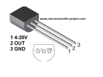
Part 4-LM 35
1.Fix the wiring as shown below.

2.Apply the coding below.
///www.arvindunimap.com

const int LM_35 = 35;
float vref = 3.3;
float resolution = vref / 1023.0;
float temp = 0;

void setup() {
   Serial.begin(9600);
}

void loop() {
   float temp = analogRead(LM_35);
   temp = (temp * resolution);
   temp =(temp * 100.0-30)/2;

   Serial.print("Temperature is : " );
   Serial.println(temp);
   delay(1000);
}
3.The output is shown below:
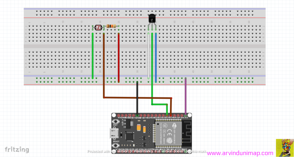
Part 5 – Using LDR and LM 35
Task of the day
Connecting the circuit
1.Green-LDR TO VCC
2.BROWN-PIN 34
3.RED-GROUND
4.WHITE-VCC
5.GREEN-LM35 TO PIN 35
6.BLUE-GROUND
7.BLACK-GROUND
8.PURPLE-VCC
2.Upload this coding
///www.arvindunimap.com

// the setup routine runs once when you press reset:
void setup() {
  // initialize serial communication at 9600 bits per second:
  Serial.begin(9600);
}

// the loop routine runs over and over again forever:
void loop() {
  // read the input on analog pin 0:
  int sensorValue = analogRead(34); //LDR
  int sensorValue1 = analogRead(35);//LM35
  // print out the value you read:
  Serial.print("LDR:"); Serial.print(sensorValue);//LDR
  Serial.print("  LM35:"); Serial.println(sensorValue1);//LM35
  delay(500);        // delay in between reads for stability
}
3.This will be the output